
EV charging: how the system works
AC charging uses the car’s onboard charger to convert electricity for the battery; DC charging supplies controlled direct current from equipment outside the car. This series explains the equipment, connections and services that determine where you can charge and how much power reaches the vehicle. Phoenix Contact: vehicle charging controllers CharIN: Combined Charging System design guide V7

How AC and DC charging work
During AC charging, alternating current passes through the charging equipment and cable to the car’s onboard charger, which converts it to direct current. The external equipment, called electric vehicle supply equipment (EVSE), provides the controlled connection and associated protection. In common Type 1 and Type 2 AC systems, control-pilot signalling tells the car the maximum current it may draw; the onboard charger can draw less. IEC 61851-1 — General requirements for conductive EV charging systems Phoenix Contact: vehicle charging controllers Argonne National Laboratory: PEV charging response characterisation (October 2025)
During DC charging, the main power conversion takes place outside the vehicle. A grid-fed station typically converts AC to regulated DC, bypassing the onboard AC charger. In CCS charging, the vehicle and station complete connection and safety checks, then exchange voltage and current requests and limits throughout the session. CharIN: Combined Charging System design guide V7
Both approaches can replenish the battery while the car is parked. AC charging commonly serves homes, workplaces and destinations where parking lasts for hours. DC fast charging serves shorter stops, such as those during a journey. The required energy and available parking time help determine which equipment is useful. U.S. Alternative Fuels Data Center — Electric vehicle charging stations
Wireless charging transfers energy through magnetic coupling rather than a plug. It requires compatible equipment on the vehicle and ground, with alignment, communication and protection designed for that system. SAE J2954 addresses stationary wireless charging for light-duty vehicles. U.S. Alternative Fuels Data Center — Electric vehicle charging stations SAE J2954 — Wireless power transfer for light-duty electric vehicles
Why the same charger gives different results
Power, measured in kW, is the rate of energy transfer. Energy, measured in kWh, is the amount transferred over time. Voltage in volts and current in amperes determine instantaneous DC power:
DC power (kW) = voltage (V) × current (A) ÷ 1,000
For an illustrative connection supplying 700 V at 400 A, the output is 280 kW. At 400 V and the same 400 A, it is 160 kW. A station needs sufficient voltage range, current capability and available power to deliver either result. A high kilowatt rating alone does not tell you what a particular car will receive.
AC charging also depends on the number of phases the car can use. In a nominal 230/400 V system, an 11 kW three-phase wallbox limited to 16 A per phase can supply about 3.7 kW to a car using one phase: 230 V × 16 A ≈ 3.7 kW, assuming a power factor near one. A car rated for 7.4 kW single-phase charging needs about 32 A on one phase, so this 16 A wallbox would limit it to about 3.7 kW. These are electrical input powers, before conversion losses. Schneider Electric: EVlink Home Smart technical data
Available power can fall when a site shares its supply among vehicles or reduces charging to accommodate other building loads. US Department of Energy: smart charge management implementation The chapters on DC fast charging and Smart charging explain how these limits are managed.
The battery and vehicle also impose limits that change during the session. Compare elapsed time and energy added over a stated charge window, with the battery temperature and charging equipment identified. Battery charging, in the battery series, explains charging curves, temperature, state of charge and the difference between energy delivered by the charger and energy stored in the battery.
Compatibility includes communication and access
A matching plug connects the hardware. Successful charging also requires compatible electrical limits, signalling and, where used, digital communication and authorisation. EV charging connectors and inlets explains regional interfaces and adapter compatibility; Charging protocols and services explains the communication and service requirements.
There are separate communication links within a networked charging system. Vehicle-to-station communication controls the charging connection. The Open Charge Point Protocol (OCPP) connects a charging station to its management system for functions such as authorisation, transaction reporting and charging limits. A private installation can operate locally, while public charging may also involve an account, payment service or roaming provider. Open Charge Alliance — Open Charge Point Protocol
Regional labels describe different things. In North America, AC Level 1, AC Level 2 and DC fast charging are common categories. IEC charging modes describe connection and control arrangements. For a useful comparison, identify AC or DC, the connector, the voltage and current capabilities, and the applicable vehicle input limit. U.S. Alternative Fuels Data Center — Electric vehicle charging stations IEC 61851-1 — General requirements for conductive EV charging systems
Find the chapter you need
Equipment and everyday charging
- EV charging connectors and inlets covers plugs, inlets, regional interfaces, adapters and port placement.
- Home EV charging covers daily energy needs, electrical installation, cable choices and home charging controls.
- DC fast charging explains station power, charging stops, site reliability, route planning and troubleshooting.
Control and services
- Smart charging explains scheduling, site load management, solar-surplus charging, fleet priorities and grid services.
- Charging protocols and services distinguishes vehicle communication, station management, Plug & Charge, roaming, authorisation and payment.
- Bidirectional EV charging explains vehicle-to-load, home, building and grid applications, including the conversion equipment and installation each requires.
Battery exchange
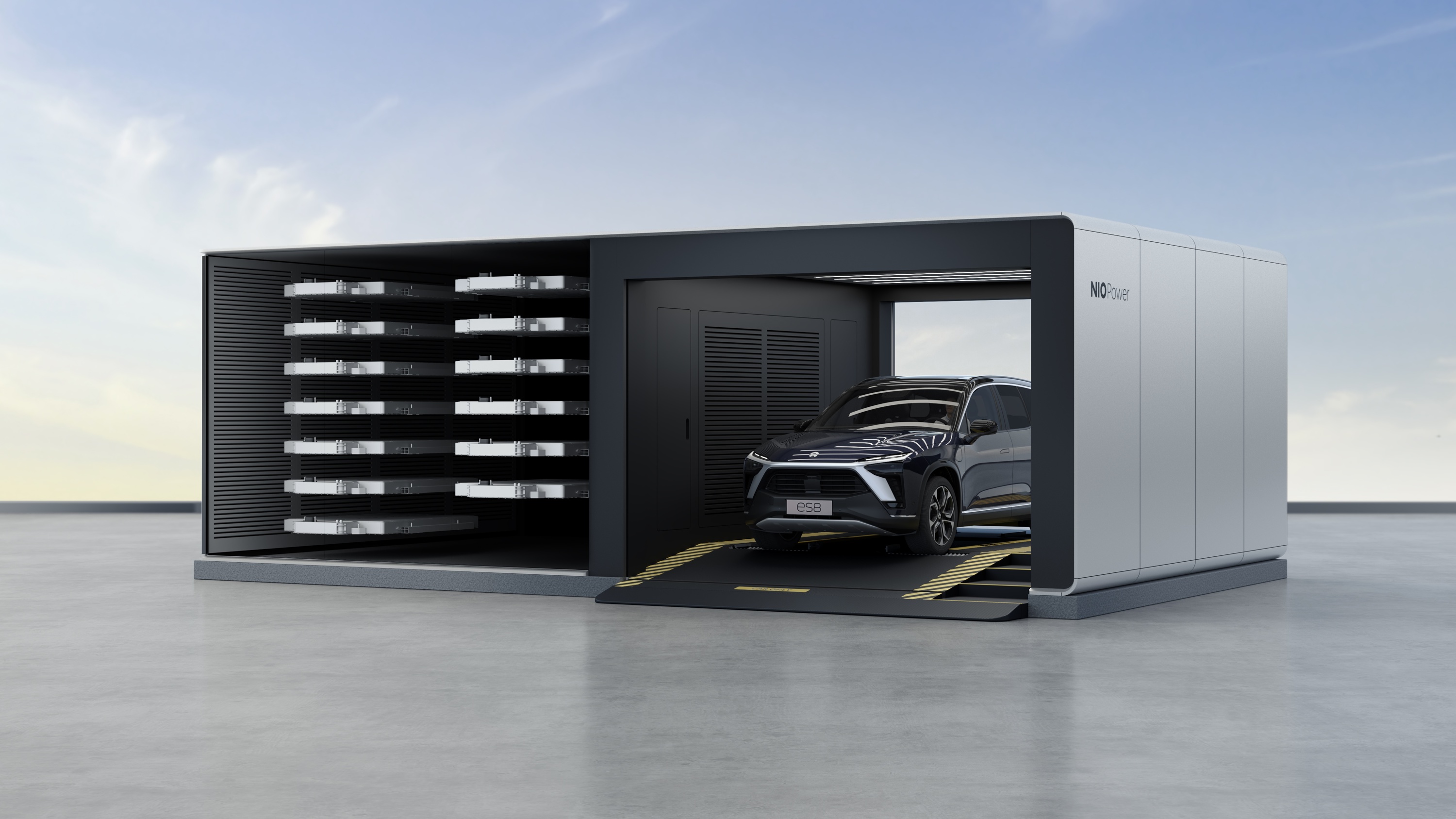
- Battery swapping explains automated pack exchange, vehicle compatibility, charged-pack inventory, ownership arrangements, safety checks and station economics.
A swap station installs a charged pack and recharges the removed pack separately. This separates the driver’s stop from the pack’s charging time; service availability also depends on a compatible pack being ready.
What to check for your own use
For home charging, establish the energy you normally need to replace before departure and have a qualified installer assess the available supply. Match the wallbox’s phase and current capability to the vehicle, and check how any load management affects the available charging time.
For journeys, check the intended sites’ connectors, vehicle access, payment options and cable reach. When comparing cars, use charging time and energy added under comparable conditions alongside the car’s consumption: the same added energy can cover different distances.
If you need backup power or grid export, verify the exact vehicle, software, external equipment and locally supported service together. Managed one-way charging changes demand; exporting energy requires a bidirectional system. US Department of Energy: managed and bidirectional charging
Sources
10
- IEC 61851-1 — General requirements for conductive EV charging systems — scope of conductive charging, connection arrangements and EVSE safety requirements.
- U.S. Alternative Fuels Data Center — Electric vehicle charging stations — charging equipment categories, use locations and inductive charging.
- Phoenix Contact: vehicle charging controllers — onboard conversion and vehicle charging-control components.
- Argonne National Laboratory: PEV charging response characterisation (October 2025) — control-pilot current limits and vehicle response during AC charging.
- CharIN: Combined Charging System design guide V7 — CCS safety sequence and voltage/current communication.
- Schneider Electric: EVlink Home Smart technical data — single-phase and three-phase voltage, current and power ratings.
- Open Charge Alliance — Open Charge Point Protocol — communication between charging stations and management systems.
- US Department of Energy: managed and bidirectional charging — managed demand, bidirectional operation and grid integration.
- US Department of Energy: smart charge management implementation — allocating charging power within site capacity and responding to building loads.
- SAE J2954 — Wireless power transfer for light-duty electric vehicles — stationary wireless charging scope and interoperability.