
Permanent-Magnet Synchronous Motors
A permanent-magnet synchronous motor (PMSM) carries a persistent magnetic field on its rotor and follows the stator’s rotating field at synchronous speed. In an EV, this architecture can provide high torque density and a broad region of high efficiency, but its details matter more than the acronym.
How a PMSM makes torque
The inverter supplies controlled three-phase current to the stator. The resulting magnetic field rotates around the air gap and pulls the rotor’s magnetic field with it. In normal synchronous operation, the rotor and stator field complete the same number of magnetic revolutions per unit of time; there is no induction-motor slip.
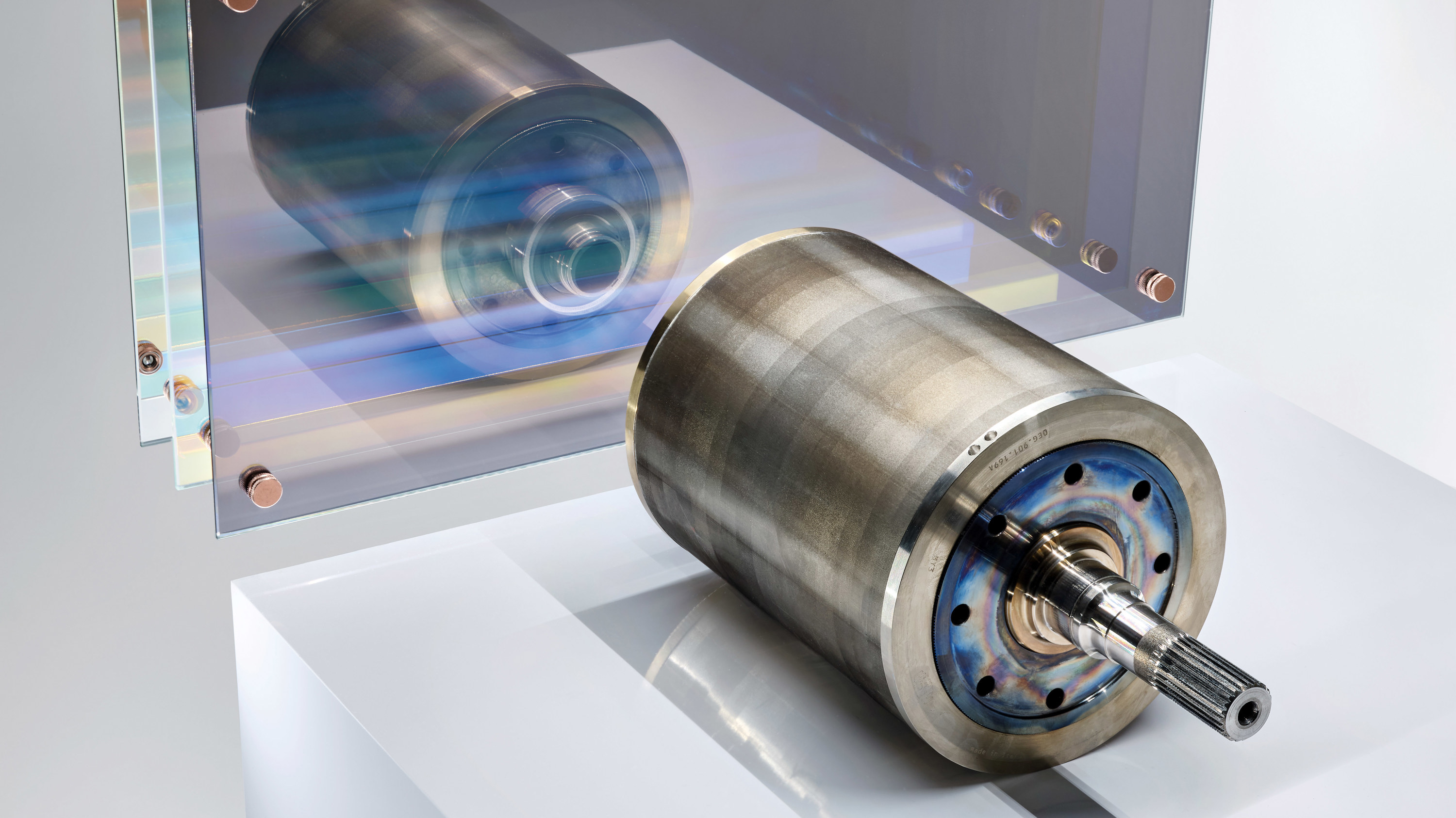
The magnets may be mounted near the rotor surface or buried inside the rotor laminations:
- A surface permanent-magnet motor has a comparatively simple magnetic geometry and low rotor saliency. Retaining magnets against high-speed centrifugal force is a central mechanical task.
- An interior permanent-magnet motor places magnets behind steel bridges or in shaped flux barriers. This protects the magnets and creates different magnetic reluctance along the rotor’s direct and quadrature axes.
That directional difference lets an interior-magnet machine produce reluctance torque as well as magnet torque. Many automotive motors described as IPMSM, permanent-magnet-assisted synchronous reluctance, or permanent-magnet synchronous reluctance machines occupy overlapping engineering territory. The label alone does not reveal how much torque comes from each mechanism.
Current control, base speed, and field weakening
Rotor position must be known or estimated so the inverter can place the stator field at the angle that produces the requested torque. Production systems commonly use a resolver or position sensor, often backed by model-based estimation.
Field-oriented control represents stator current on two rotating axes. The torque-producing and flux-changing components can then be controlled separately. Below base speed, the controller usually seeks high torque per ampere while respecting current, voltage, thermal, and demagnetization limits.
At higher speed, the rotor magnets generate increasing back electromotive force. Once the available DC-bus voltage becomes the constraint, the inverter applies a current component that opposes part of the magnet flux. This field weakening extends speed, but consumes current capacity and adds loss. An interior-magnet rotor’s saliency can help create a useful constant-power speed range.
During regenerative braking, commanded current produces negative shaft torque and the inverter returns electrical power to the battery within traction and battery limits.
Why PMSMs are efficient and compact
The rotor field does not require continuous electrical excitation, so there is no induction-cage loss or wound-field excitation loss in normal operation. Strong magnets and an optimized magnetic circuit can deliver high air-gap flux from a compact rotor. Those properties support high torque and power density.
Efficiency is still an operating map, not a fixed motor attribute. Stator copper loss dominates many high-torque points; iron, magnet eddy-current, windage, bearing, inverter, and gear losses become important elsewhere. At very high speed, field-weakening current can materially change the system result.
Magnets, temperature, and material supply
High-performance traction motors commonly use neodymium-iron-boron magnets because of their magnetic strength. Dysprosium, terbium, or other additions may be used selectively to retain coercivity at temperature. Samarium-cobalt and ferrite magnets are alternatives for particular temperature, cost, or supply-chain goals, but each changes the size, magnetic circuit, and control trade-offs.
Magnets have thermal limits. Excessive rotor temperature or an adverse magnetic field can cause partial, irreversible demagnetization. Engineers manage that risk through magnet grade, segmentation, rotor geometry, current limits, and cooling. Rare-earth mining, processing concentration, price volatility, and magnet manufacturing also affect the architecture decision.
The statement “PMSMs require rare earths” is therefore too broad: permanent magnets do not have to contain rare-earth elements. The more accurate point is that many high-power-density automotive PMSMs use rare-earth magnets today.
Windings and manufacturing
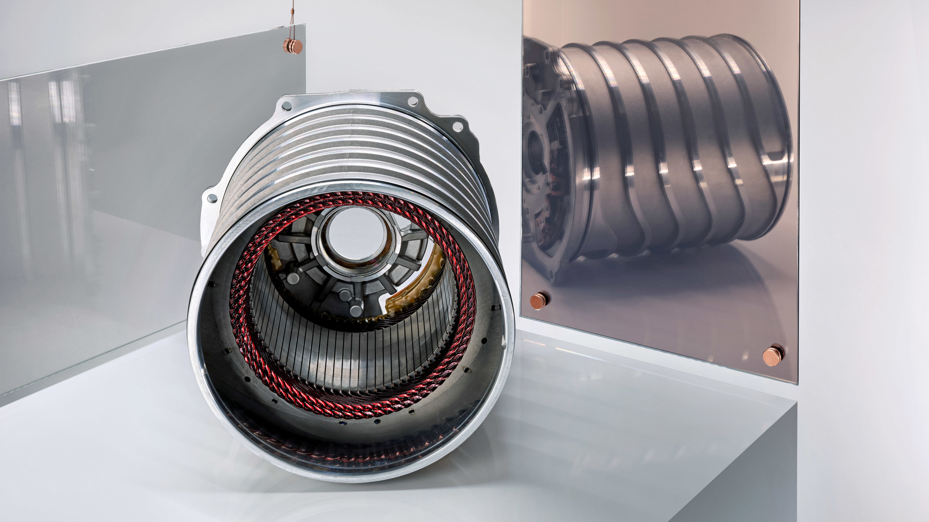
The stator may use stranded-wire or formed rectangular conductors. Hairpin windings can raise slot copper fill, improve manufacturing repeatability, and create direct thermal contact, but larger conductors can suffer additional AC loss at high electrical frequency. Winding pitch, slot and pole count, end-turn length, insulation, joining, and cooling are co-designed with the rotor and inverter.
Magnet placement is equally demanding. Rotor bridges must survive maximum speed while limiting magnetic leakage. Magnet segmentation can reduce eddy-current loss, and sleeves or other retention structures may be needed in high-speed designs.
Coasting and secondary axles
A spinning permanent-magnet rotor continues to create magnetic flux. It therefore produces back EMF and core or magnet-related losses even when commanded torque is zero. Back EMF by itself does not imply large braking torque if phase current is prevented, but the inactive drive unit still has bearing, seal, gear, oil, and electromagnetic losses.
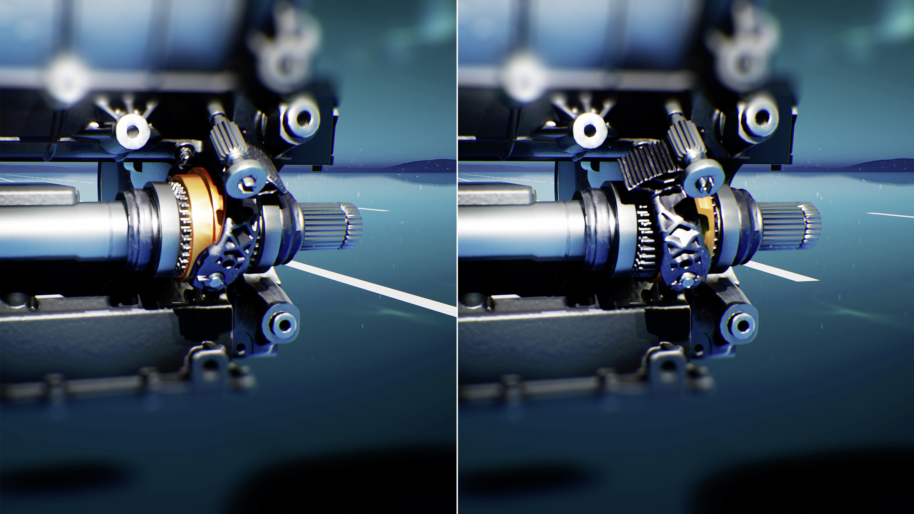
EV makers manage those losses through inverter control, low-loss motor design, a disconnect clutch, or a different motor type on the secondary axle. The best solution depends on cost, response time, packaging, and how often all-wheel drive is needed.
What the name does not tell you
“PMSM” does not specify surface or interior magnets, magnet chemistry, pole count, winding type, cooling, maximum speed, field-weakening range, peak duration, or the efficiency map. Those design choices determine how the motor behaves in a vehicle.
Porsche’s Taycan shows one production approach: permanently excited synchronous motors, hairpin stator windings, liquid cooling, and inverter control are integrated with axle-specific transmissions. Other EVs use different magnet layouts, winding methods, or mixed-motor all-wheel-drive systems. Motor topology should be read as one part of the complete drive-unit design.
For a detailed manufacturer discussion of compact PMSM construction, the existing Lucid technical video remains useful:
Return to Electric Motors and Drive Units.