
Axial-Flux Permanent-Magnet Motors
An axial-flux permanent-magnet motor uses a disc-like magnetic circuit in which the main air-gap flux runs parallel to the shaft. It follows the same synchronous electromagnetic principles as a radial-flux PMSM, but its geometry trades motor length for diameter and can create high torque from a short package.
Geometry, not a new source of torque
“Axial flux” describes the direction of the main magnetic path. “Permanent-magnet synchronous” describes the rotor excitation and its relationship to the rotating stator field. These are separate classifications: axial-flux induction and reluctance machines are possible, although current high-performance automotive attention is concentrated on axial-flux permanent-magnet machines.
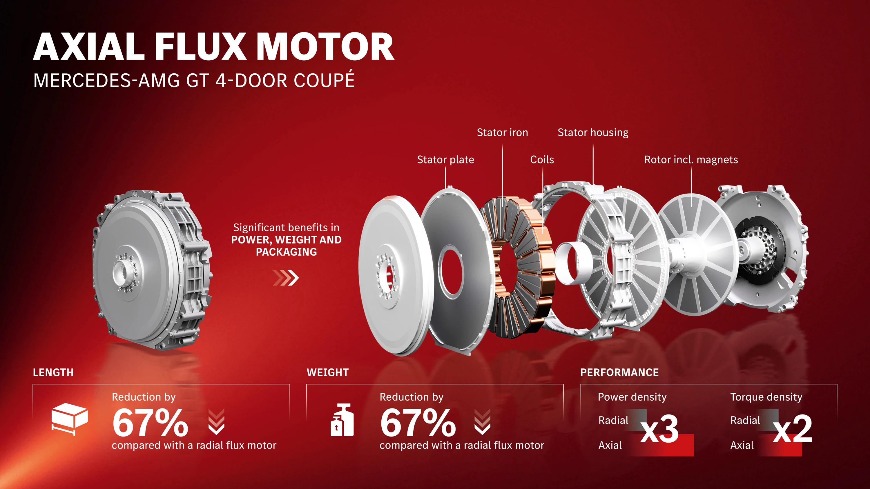
Several layouts exist. A machine may use one rotor between two stators, one stator between two rotors, or multiple repeating stages. YASA’s yokeless-and-segmented-armature topology places a segmented stator between two permanent-magnet rotor discs. Both sides of the stator contribute torque, and the usual continuous stator yoke is removed.
How the motor produces torque
An inverter supplies multiphase current to the stator windings. A resolver, encoder, or position estimator tells the controller where the rotor field is, and field-oriented control sets the phase-current vector. The two rotor discs follow the commanded rotating field at synchronous speed.
Torque benefits from the machine’s active radius. Much of the electromagnetic shear acts farther from the shaft than it would in a smaller-diameter radial machine, increasing the lever arm. A dual-air-gap design can use both stator faces. Those advantages can yield high torque per unit of axial length and, in a carefully optimized design, high torque and power density by mass or volume.
The result is not automatic. Diameter, air-gap flux, current loading, cooling, rotor stress, bearings, inverter capability, and duty cycle set the actual output. Comparing an axial-flux motor with a radial-flux motor requires the same peak duration, continuous thermal conditions, coolant temperatures, inverter limits, and measurement boundary.
Packaging and performance
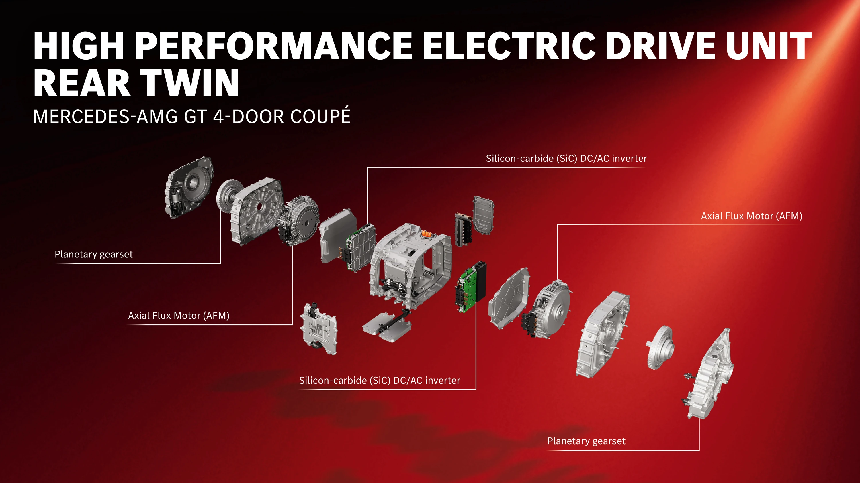
The thin shape can free space along an axle or allow several motors and gear paths to fit into a compact high-performance drive unit. This is valuable when motor length is more constrained than diameter.
High torque density can reduce drive-unit mass, but the complete system includes rotor supports, bearings, housing, coolant circuits, inverter, and transmission. A motor-only power-density claim should not be treated as drive-unit or vehicle power density.
Continuous output depends heavily on heat removal. Axial-flux stators are enclosed between rotor discs in common layouts, so a conventional outer water jacket may have a long thermal path to the copper. Direct oil cooling or cooling close to the segmented windings can shorten that path and support repeated high load.
Mechanical and thermal challenges
The rotor discs attract the stator with substantial axial force. Opposed rotors can balance net force when they are aligned correctly, but housing stiffness, bearing arrangement, rotor flatness, and assembly tolerances must keep both air gaps small and even. Thermal expansion, vibration, and manufacturing variation make that a demanding production problem.
The wide disc also requires careful control of rotor stress and deflection at speed. Magnets must be retained, eddy-current loss managed, and torque ripple and noise controlled through pole, slot, magnet, and winding design.
Cooling fluid must be electrically and chemically compatible with insulation, adhesives, magnets, seals, and bearings. Direct cooling adds pumps, galleries, filtration, sealing, and drag. Strong cooling can raise continuous power, but it also consumes auxiliary energy.
Permanent magnets bring the same temperature, demagnetization, cost, and supply-chain questions found in radial PMSMs. Axial flux does not remove those issues; it changes the geometry in which engineers solve them.
From specialist technology to series production
Mercedes-Benz began large-scale production of its axial-flux motor at Berlin-Marienfelde in June 2026. The company identifies the new battery-electric Mercedes-AMG GT 4-Door Coupé as the motor’s first series-production vehicle application. Its three axial-flux motors are integrated into high-performance electric drive units with compact planetary reduction gearing.

Mercedes-Benz says the production system requires 98 process steps, with tight control of the dual-rotor assembly and stator position. That industrial effort illustrates why axial-flux performance cannot be separated from manufacturability.
YASA, acquired by Mercedes-Benz in 2021, developed the yokeless-and-segmented-armature approach behind the current programme. Other axial-flux architectures and suppliers use different stator cores, rotor counts, windings, materials, and cooling, so “YASA” should not be used as a synonym for every axial-flux motor.
Where axial flux fits
Axial-flux machines are compelling where axial space and torque density justify demanding cooling and production processes. Performance cars are an early fit because compactness, repeated output, and mass carry high value.
They are not a universal successor to radial motors. Radial-flux machines benefit from mature tooling, established supply chains, familiar cooling jackets, and scalable production across a wide power range. Future adoption will depend on complete drive-unit cost, continuous performance, manufacturing yield, durability, and serviceability—not on a single peak power-density figure.
For a visual discussion of axial-flux construction, the existing Munro Live video remains available:
Return to Electric Motors and Drive Units.