
Electric Motors and Drive Units
An electric vehicle's traction motor belongs to a tightly coupled system in which the battery, inverter, motor, cooling circuit, reduction gears, differential, tyres, and control software all determine how efficiently electrical energy becomes motion.
This hub separates three questions that are often mixed together: how different motor families create torque, how a drive unit is constructed and controlled, and how the complete vehicle uses and measures that hardware.
The energy path from battery to road
The high-voltage battery supplies direct current. A traction Traction inverters switches that DC into controlled multiphase current—normally three-phase AC—whose amplitude, frequency, and phase set the motor's torque and speed. Motor control and efficiency maps translates the driver's request and vehicle limits into the current commands followed by the inverter.
Inside the motor, current in the stationary windings creates a rotating magnetic field. The rotor follows or interacts with that field and turns the output shaft. The choices behind the stator, rotor, windings, laminations, insulation, air gap, bearings, and manufacturing tolerances are covered in EV motor construction and windings.
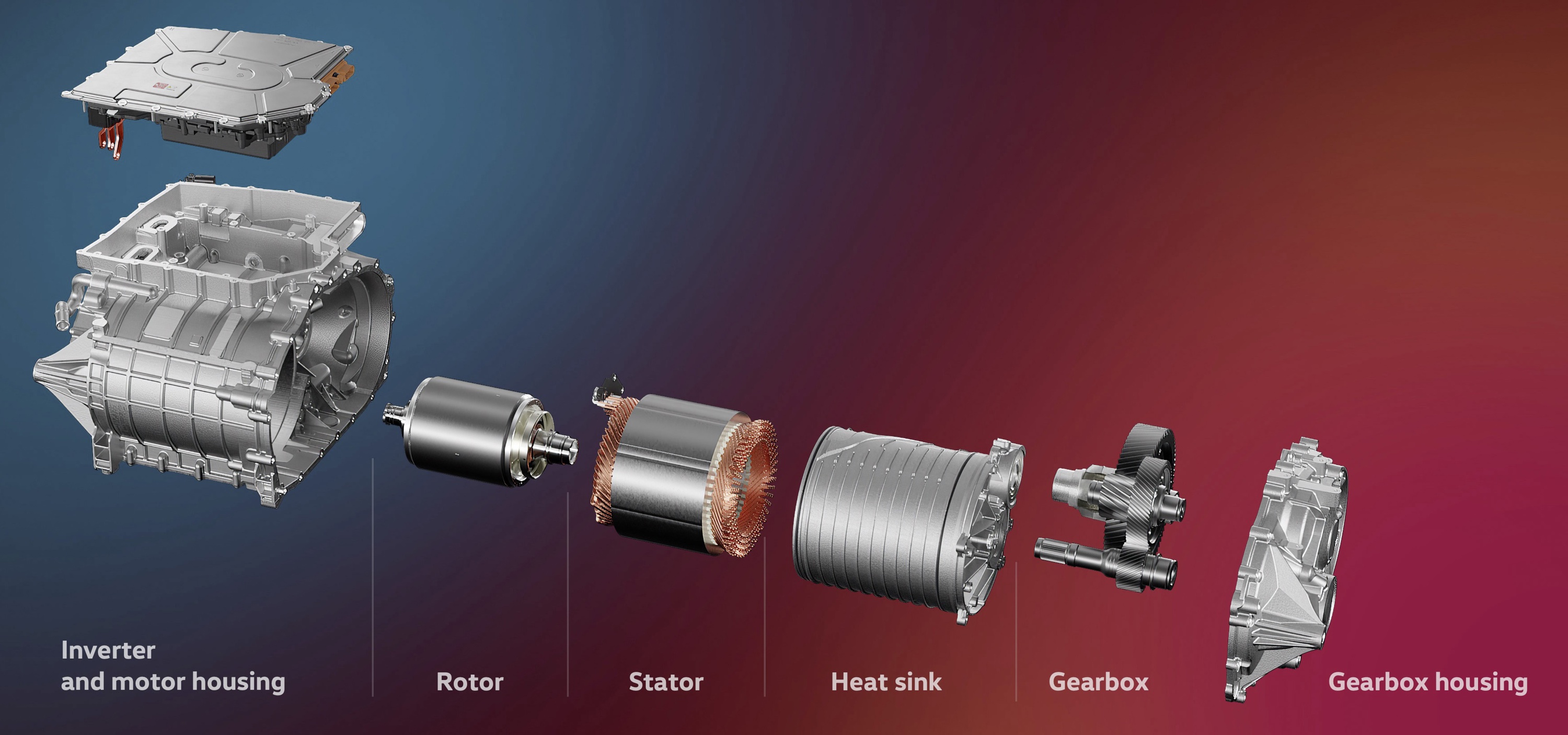
A fixed reduction gear normally trades motor speed for wheel torque. The differential allows the driven wheels to turn at different speeds in a corner. In a modern Integrated electric drive units, the motor, inverter, reduction gears, differential, lubrication, and cooling passages may share one compact housing.
How an AC traction motor makes torque
Most EV traction motors have two main electromagnetic parts: a stator that stays still and a rotor that turns across a narrow air gap. Three stator phases are energized in sequence, producing a magnetic field that rotates around the air gap.
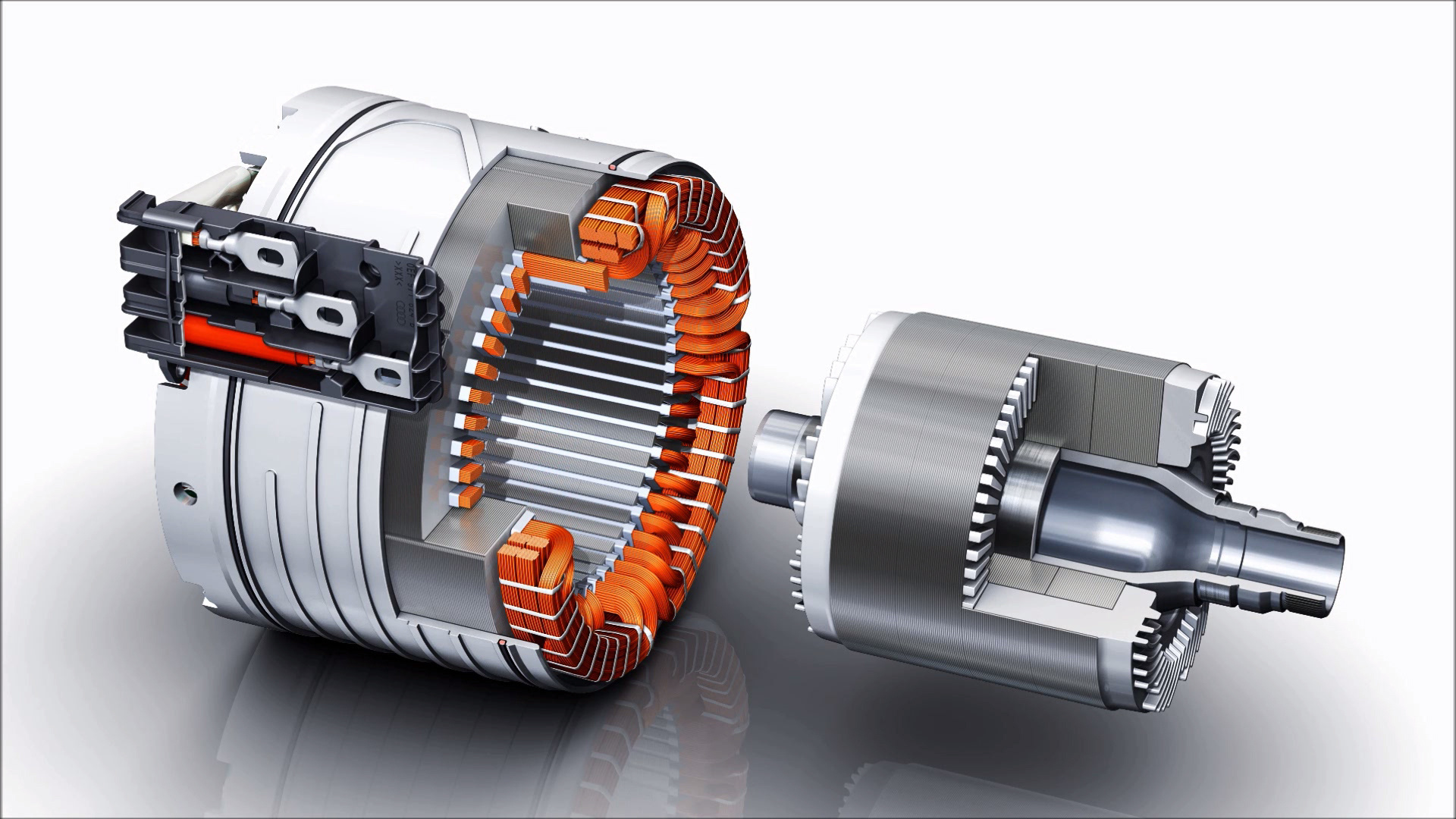
The motor family is defined mainly by how the rotor obtains its magnetic field and how that field moves relative to the stator field:
- A permanent-magnet synchronous motor carries magnets in or on the rotor.
- An electrically excited synchronous motor creates the rotor field with a DC-fed winding.
- An induction motor induces current in a conductive rotor cage; the rotor must run at a different speed from the stator field to produce torque.
- A reluctance motor produces torque because its rotor is easier to magnetize along some directions than others.
"Synchronous" describes the rotor's speed relative to the rotating stator field. It does not mean that the rotor and stator are mechanically connected. Bearings support the rotor, while the air gap keeps the electromagnetic parts physically separate.
Torque, speed, and power
Torque is the twisting force at the shaft. Power is the rate at which the motor does work:
power = torque × rotational speed
This relationship explains the characteristic EV torque curve. From standstill to a motor's base speed, the inverter can usually supply enough current for a broad constant-torque region. Above base speed, voltage and back electromotive force become the main constraints. The controller weakens the effective magnetic field so the motor can turn faster, while available torque falls. Power can remain roughly constant across part of this higher-speed region.
The exact curve is bounded by battery power, inverter voltage and current, motor temperature, rotor speed, and mechanical limits. A quoted peak output may be available for only seconds. Continuous output is the power the complete drive unit can sustain at defined cooling and environmental conditions. EV motor testing and ratings explains why test boundary and duration must accompany a power figure.
During regenerative braking, the same machine operates as a generator. Wheel torque drives the rotor, the inverter controls generator current, and electrical energy returns to the battery when battery temperature, state of charge, traction, and system limits allow it.
The main motor families in EVs
Permanent-magnet synchronous motors are common because they can combine high power density with high efficiency across a useful portion of the driving map. Interior-magnet designs can produce both permanent-magnet torque and reluctance torque. Their fixed rotor flux also creates field-weakening, fault-voltage, material-supply, and thermal design challenges.
Induction (asynchronous) motors contain no rotor magnets or electrical contacts. Their rotor field exists only when stator excitation induces current in the cage. They are mechanically rugged and can have low electromagnetic drag when de-energized, which makes them useful both as primary traction motors and as secondary-axle motors. Rotor current, however, adds heat and loss.
Electrically excited synchronous motors replace permanent magnets with a controllable rotor electromagnet. Turning the field current up or down gives engineers another control variable, including efficient field weakening at high speed. The price is an excitation system, rotor copper loss, and—where brushes and slip rings are used—additional mechanical and durability requirements.
Reluctance motors include magnet-free synchronous-reluctance and switched-reluctance machines as well as permanent-magnet-assisted designs. They exploit directional differences in the rotor's magnetic reluctance. Simple magnet-free rotors are possible, but torque density, inverter demand, torque ripple, acoustics, and control must be evaluated for the complete system.
Axial-flux permanent-magnet motors describe a different magnetic geometry rather than a separate source of rotor excitation. Most automotive axial-flux motors are permanent-magnet synchronous machines whose main flux crosses the air gap parallel to the shaft. Their large active radius and short axial package can provide high torque density, but cooling, air-gap control, axial forces, and mass production are demanding.
Why no motor type is simply best
A motor does not have one efficiency number. It has an efficiency map covering speed and torque, and a vehicle visits different parts of that map during urban driving, motorway cruising, climbing, towing, and hard acceleration. The inverter and gearbox have their own maps, so engineers optimize the complete drive unit against the intended duty cycle.
The main losses also change with operating point:
- winding resistance creates copper loss that rises strongly with current;
- changing magnetic fields create hysteresis and eddy-current loss in electrical steel and other conductive parts;
- induction and electrically excited rotors add rotor copper loss;
- the inverter has conduction and switching losses;
- bearings, seals, gears, oil pumps, and oil churning create mechanical losses.
Motor selection therefore balances efficiency over the useful map, power and torque density, material cost and supply, inverter rating, cooling demand, maximum speed, acoustics, controllability, manufacturing yield, durability, and serviceability. A slightly less efficient motor at its best point may produce a more efficient vehicle if its useful high-efficiency region better matches the vehicle's driving load.
One motor or several
A single motor can drive the front or rear axle through a differential. Two motors normally provide independently controlled front- and rear-axle torque, enabling all-wheel drive without a mechanical propshaft. Manufacturers may use the same motor type at both axles or mix types to exploit different efficiency and free-rolling characteristics.
Three-motor systems usually place one motor on one axle and two independently controlled motors on the other. Four-motor systems may use one motor for each wheel or two motors per axle connected through separate gear paths. Independent motors create the hardware opportunity for rapid torque vectoring, but the actual capability depends on sensors, inverter capacity, tyre grip, thermal limits, gearing, and control software.
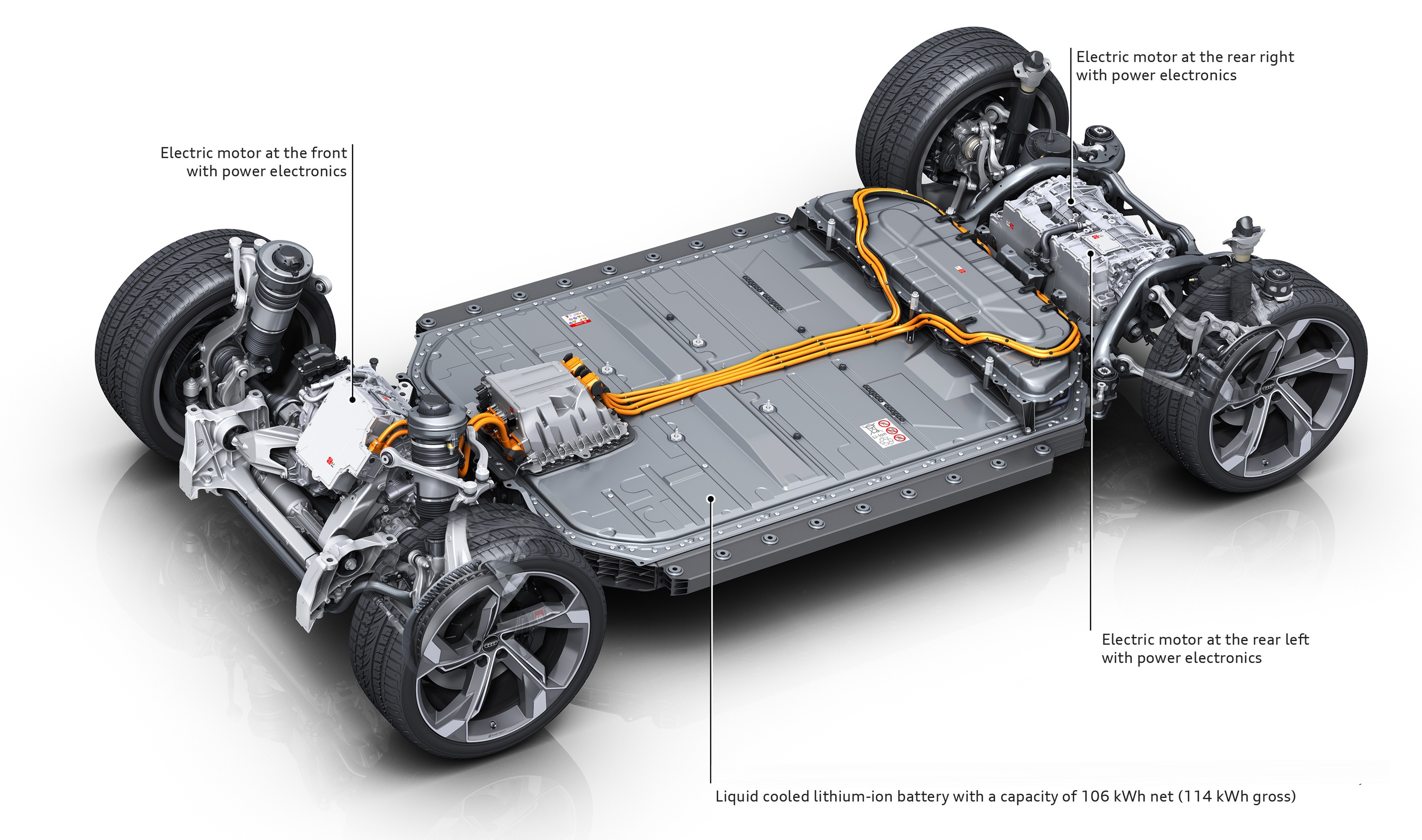
Extra motors are not free performance. They add mass, cost, cooling loads, inverters, cables, bearings, and parasitic losses. Disconnect clutches and de-energized induction motors can reduce the cruising penalty on a secondary axle. Multi-motor EV architectures examines single-, dual-, tri-, and quad-motor architectures in detail.
Reading EV motor specifications
Useful motor data should answer more than "how many kilowatts?" Check whether a figure is peak or continuous, whether it applies to one motor, one axle, or the complete vehicle, and whether quoted torque is measured at the motor shaft or after gear reduction at the wheels.
The most informative engineering data include:
- motor topology and location;
- peak and continuous power under stated conditions;
- peak torque and maximum motor speed;
- DC-bus voltage, inverter current, and semiconductor type;
- gear ratio and driveline efficiency;
- motor-and-inverter efficiency maps for motoring and regeneration;
- cooling method and thermal limits;
- whether secondary motors can be de-energized or disconnected;
- the measurement boundary, temperatures, and test procedure.
These details explain why two vehicles with similar peak output can differ in motorway consumption, repeated acceleration, towing performance, noise, and sustained high-speed capability.
Read the series in order
Start with the motor families:
- Induction (asynchronous) motors
- Permanent-magnet synchronous motors
- Electrically excited synchronous motors
- Reluctance motors
- Axial-flux permanent-magnet motors
Then follow the hardware and energy-control chain:
- EV motor construction and windings
- Traction inverters
- Motor control and efficiency maps
- Motor cooling
- Reduction gears and transmissions
- Integrated electric drive units
Finish with vehicle architecture and engineering evidence:
The navigation tabs use this same order.