
EV battery management systems: monitoring, estimation and control
An EV's battery management system (BMS) turns voltage, current and temperature measurements into estimates of battery state and limits on charging and driving power. It also supervises the battery's electrical connection to the vehicle and responds to faults.
This chapter explains those measurements and decisions. Battery Pack and Configuration covers the electrical arrangement they act on.
What the BMS measures
Cells connected directly in parallel share a terminal voltage. The BMS therefore normally measures each parallel group as one series position. A hypothetical 108s4p pack contains 432 physical cells but has 108 series-group voltages to monitor.
Those group readings reveal differences that total pack voltage can hide. A high reading in one group can offset a low reading elsewhere, leaving the total looking normal. The controller needs the individual readings to identify which group is approaching a limit.
Alongside these voltages, the BMS uses pack-current measurements and temperature sensors. Temperature readings describe the sensor locations; they do not directly measure every point inside every cell. Pack-level monitoring also checks high voltage and electrical isolation, while diagnostic circuits report connection and switching conditions. Texas Instruments: automotive battery-management systems
Current integrated over time helps estimate charge remaining. Voltage and temperature constrain the permitted current.
How the hardware is organised
BMS electronics can be centralised, modular or distributed. In Nexperia's classification, a centralised BMS manages the whole pack from one central unit. A modular arrangement divides monitoring and control among units responsible for subsets of modules, which report to a central controller. A distributed arrangement places monitoring and balancing at individual cells or small groups, linked by a communication bus. Nexperia: Battery Management System technical guide
NXP's 2023 reference design for 800 V applications illustrates the hardware roles, with cell-monitoring units, a battery-management unit and a battery junction box. NXP: 800 V BMS reference-design user guide (2023)
Monitoring units and the controller
Cell-monitoring units (CMUs) measure cell-group voltages and temperature-sensor inputs close to the cells. They can also provide balancing circuits. The battery-management unit (BMU) collects these readings and runs the control software. NXP: 800 V BMS reference-design user guide (2023)
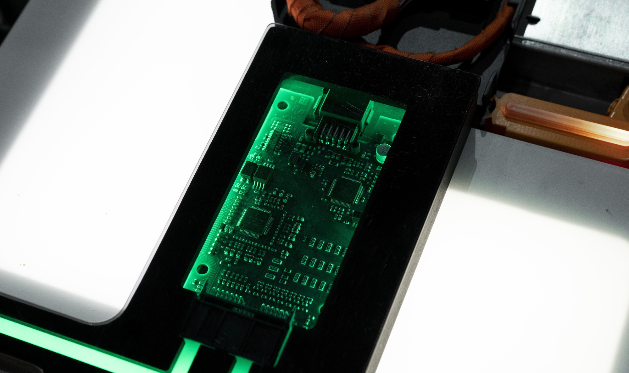
Wired links can connect monitoring devices in a daisy chain. A redundant communication path can preserve access to measurements after a link failure, provided the hardware and control strategy support it. Texas Instruments: functional safety in battery management (2020)
A wireless BMS replaces communication wiring between the cell-monitoring electronics and the central controller with a radio link. Analog Devices describes this monitor-to-controller link in its wireless BMS system. Analog Devices: wireless battery management (2022) Voltage sensing and balancing remain local electrical functions at the cells. NXP: 800 V BMS reference-design user guide (2023)
The battery junction box
The battery junction box (BJB) contains the pack's high-current connections and switching hardware; its sensing arrangement varies. TI distinguishes a conventional junction box whose measurement wires run to the BMU from an intelligent junction box with a local pack monitor. Texas Instruments: intelligent battery junction boxes (2022)
Synchronising voltage and current samples matters: readings taken at different moments during a changing load can distort calculated power and resistance. Texas Instruments: intelligent battery junction boxes (2022)
Estimating charge, energy, power and health
The BMS calculates quantities that sensors cannot read directly. Their definitions and reference conditions determine what a displayed percentage or diagnostic value means.
State of charge
State of charge (SOC) expresses the remaining electric charge relative to a reference charge capacity, usually as a percentage. Coulomb counting tracks charge entering and leaving by integrating current over time. Analog Devices: SOC and SOH estimation techniques (2023)
For a simplified example, a constant discharge current of 10 A for 30 minutes removes 5 Ah. Against a fixed reference capacity of 100 Ah, that represents five percentage points of SOC. This calculation tracks charge; calculating energy also requires voltage.
A persistent current-sensor offset produces an accumulating error as the current is integrated over time. Analog Devices' analysis of coulomb-counter accuracy describes offset and other measurement errors. Analog Devices: accuracy of coulomb-counting systems (2000)
The calculation also needs a starting SOC. Voltage can help correct the estimate, but it responds to load and temperature. Model-based estimators such as Kalman filters combine measurements with predicted battery behaviour to update SOC. Analog Devices: SOC and SOH estimation techniques (2023)
LFP cells make voltage-based estimation particularly difficult through the flat part of their open-circuit-voltage curve. Hysteresis also means voltage depends on the preceding charge or discharge path. Che and colleagues' 2025 study examines these difficulties and the use of relaxation measurements to correct SOC estimates. Che et al.: Enhanced SOC Estimation for LFP Batteries (2025) Cell Chemistry and Components explains the underlying materials.
The dashboard percentage is a further mapping of the battery estimate onto a driver-facing scale. Displayed 100% and 0% need not coincide with the cell operating limits or the end of all accessible energy; Battery Buffer and Usable Capacity explains the distinction.
An open-circuit-voltage measurement after a sufficiently long rest can provide a new SOC reference, using the cell's voltage–SOC relationship. Analog Devices: SOC and SOH estimation techniques (2023) Correcting the estimate can therefore change the displayed percentage without adding energy or restoring lost cell capacity. Charging routines should follow the vehicle's manual.
Remaining energy and state of energy
Remaining usable energy is expressed in kWh. State of energy (SOE) can instead be expressed as a fraction or percentage: MathWorks defines it as remaining energy divided by total reference energy. The reference and discharge conditions must be clear when comparing values. MathWorks: state-of-energy estimator
SOC and SOE need not follow identical percentages because voltage varies during discharge. Two batteries at the same SOC can also have different amounts of energy remaining simply because their capacities differ.
State of power
State of power (SOP) describes the power a battery can accept or deliver within its limits over a specified duration. Charge and discharge capabilities are calculated separately. A brief peak and a sustained output are different operating demands.
A power estimator considers how cell voltage will respond to current, using factors such as SOC, temperature and resistance. The allowed pack current must respect the limiting cell groups as well as pack-level limits. MathWorks' battery-power model illustrates this calculation over a defined prediction period. MathWorks: battery power estimator
State of health
State of health (SOH) describes capability relative to a reference, commonly the battery when new. Capacity retention and the ability to deliver power are different aspects of health. An SOH percentage needs a defined metric and comparison basis. Analog Devices: SOC and SOH estimation techniques (2023)
Tesla's US manual for the 2017–2023 Model 3 distinguishes a battery-health evaluation using BMS data from an optional test that reports energy retention compared with new. The manual notes that the test feature may not be available on every vehicle. Tesla Model 3 (2017–2023): high-voltage battery health, US manual
Battery Degradation covers capacity loss and resistance growth in more detail.
Connecting and protecting the high-voltage circuit
Contactors are electrically operated switches that connect the battery to the vehicle's high-voltage circuit. Before enabling that connection, control logic checks the relevant measurements and fault signals.
Precharge
High-voltage equipment such as the inverter contains capacitors. Connecting an uncharged DC-link capacitor directly to the battery can produce a large inrush current, damaging components or welding contactor surfaces. A conventional precharge circuit charges it through a resistor first. Texas Instruments: high-voltage precharge circuits (2021)
In TI's illustrated arrangement, the negative main contactor and the precharge path close while the positive main contactor remains open. Once the load-side voltage approaches battery voltage, the circuit transitions to the main contactors carrying the current, with the precharge branch open. Texas Instruments: high-voltage precharge circuits (2021)
Battery-side and load-side voltage measurements let the controller follow precharge and support switching diagnostics. Texas Instruments: intelligent battery junction boxes (2022) The readings must be interpreted with the circuit's operating state: precharge brings the two voltages close while the positive main contactor is still open, so matching voltages alone do not establish that it has closed. Texas Instruments: high-voltage precharge circuits (2021)
Isolation and interlock monitoring
Isolation monitoring checks electrical resistance between the high-voltage circuit and the chassis. It detects an unwanted conductive path, rather than simply checking whether a connector is seated. NXP's reference BJB includes battery-to-chassis isolation monitoring. NXP: 800 V BMS reference-design user guide (2023)
The high-voltage interlock loop (HVIL) is a separate low-voltage circuit passing through monitored connections. TI's reference design distinguishes closed connections, open connections and short-circuit faults, then reports their state to vehicle safety logic. Texas Instruments: high-voltage interlock reference design (2024) An interlock fault and an isolation fault therefore describe different problems, even if either can prevent a vehicle from enabling high voltage.
Responses depend on the fault
Protection decisions depend on the fault and the vehicle's operating state. Responses can include limiting power, stopping charging, warning the driver or preventing reconnection. Severe overcurrent may use a faster protection path: TI describes a dedicated pack-monitor output that can trigger a pyrotechnic disconnect. Texas Instruments: intelligent battery junction boxes (2022)
Functional safety also addresses failures in the monitoring and control electronics themselves. ISO/TR 9968:2023 provides an informative framework for applying ISO 26262 methodology to rechargeable energy-storage systems, including the BMS, cells and connections. ISO/TR 9968:2023: functional safety of rechargeable energy-storage systems
Opening contactors isolates the external circuit but leaves energy stored in the cells and voltage on internal conductors. Battery Safety covers internal cell failures, physical containment and protection against propagation.
How limits affect charging and driving
The BMS supplies permitted charge and discharge limits to the vehicle's other controllers. During fast charging, the vehicle's charging controller uses the battery limits when requesting current from the station. Charger capability and vehicle hardware can impose further limits; Battery Charging and Charging Performance explains their effect on the complete charging curve.
As a cell group's voltage approaches its upper limit, the permissible charging current falls. During discharge, voltage sag in a limiting group can instead restrict the current available for propulsion. The driver can therefore encounter reduced acceleration while energy remains in the pack. MathWorks: battery power estimator
Regenerative braking sends energy back to the battery and must respect its charge-power limit. Automatic friction-brake compensation depends on the vehicle and settings. Tesla's US manual for the 2024-and-later Model 3, for example, describes a selectable function that applies the regular brakes when regeneration is limited by a cold or fully charged battery. That compensation function may not operate when the brakes are extremely hot. Tesla Model 3 (2024+): braking and stopping, US manual
Using temperature measurements, the BMS communicates heating and cooling requests to the thermal-management system, alongside charge and discharge limits. Nexperia: Battery Management System technical guide Battery Thermal Management explains the heat paths and preconditioning strategies.
Balancing and diagnostic information
Balancing reduces differences in charge level between series-connected groups. In a passive system, a resistor dissipates energy from selected groups so that others can continue charging. Analog Devices: passive battery cell balancing (2016) Balancing changes the distribution of charge; SOC calibration changes the estimate. The methods and their limits belong in Cell Balancing.
Diagnostic information helps distinguish a cell problem from a sensing or connection problem. For example, a disconnected voltage-sense wire can remove a valid reading without the cell itself having failed. Communication faults can likewise make measurements unavailable to the controller, which may then lack the information needed to permit continued operation. Texas Instruments: functional safety in battery management (2020)
When interpreting a diagnostic percentage, check whether it is an estimate from normal operation or a test result, what it measures, and which reference it uses.
Sources
18
- Texas Instruments: automotive battery-management systems — monitoring and control functions.
- Nexperia: Battery Management System technical guide — hardware arrangements and thermal-control coordination.
- NXP: 800 V BMS reference-design user guide (2023) — CMU, BMU and BJB roles in an 800 V reference design.
- Texas Instruments: intelligent battery junction boxes (2022) — junction-box sensing, timing and overcurrent protection.
- Analog Devices: wireless battery management (2022) — communication between monitoring electronics and the controller.
- Analog Devices: SOC and SOH estimation techniques (2023) — charge integration, SOC estimation and health references.
- Analog Devices: accuracy of coulomb-counting systems (2000) — current-measurement errors in coulomb counting.
- Che et al.: Enhanced SOC Estimation for LFP Batteries (2025) — flat voltage characteristics, hysteresis and relaxation-based estimation.
- MathWorks: state-of-energy estimator — state of energy as a ratio.
- MathWorks: battery power estimator — charge and discharge power over a specified duration.
- Tesla Model 3 (2017–2023): high-voltage battery health, US manual — BMS-based evaluation and energy-retention testing.
- Texas Instruments: high-voltage precharge circuits (2021) — capacitive inrush and conventional precharge.
- Texas Instruments: high-voltage interlock reference design (2024) — connection monitoring and interlock faults.
- Texas Instruments: functional safety in battery management (2020) — sensing failures, communication and redundancy.
- ISO/TR 9968:2023: functional safety of rechargeable energy-storage systems — scope of the functional-safety technical report.
- Sharp et al.: thermal runaway of lithium-ion cells (2022) — internal cell failures and thermal runaway.
- Tesla Model 3 (2024+): braking and stopping, US manual — vehicle-specific friction-brake compensation.
- Analog Devices: passive battery cell balancing (2016) — passive balancing and cell differences.