
Suspension layouts, geometry and wheel control
A suspension layout determines how the wheel is constrained as it moves, steers and carries force. Labels such as MacPherson, double wishbone and multi-link describe arrangements of links and joints; they do not, by themselves, predict the complete ride and handling behavior introduced in the EV suspension overview.
Kinematics and compliance
A wheel carrier can translate and rotate in three dimensions. Suspension links constrain most of those degrees of freedom while allowing a designed path through bump and rebound. Kinematics describes that ideal geometric motion. Elastokinematics, or compliance kinematics, describes the additional motion caused when bushings, joints, links, subframes and the body deflect under tyre force.
Both matter. A layout can have desirable camber on a geometry rig yet gain unwanted toe under braking because a bushing deflects. Conversely, carefully directed compliance can absorb an impact or add stabilizing toe under lateral load. Modern development therefore combines multibody simulation, stiffness models, kinematics-and-compliance testing, durability work and road calibration. SAE: three-dimensional analysis of major suspension layouts SAE: suspension kinematics and data-driven compliance
The main geometry terms are:
- Camber: wheel inclination viewed from the front. Its change through wheel travel and body roll affects how the tyre meets the road.
- Toe: whether the wheels point inward or outward viewed from above. Unwanted toe change with wheel travel is commonly called bump steer.
- Caster, steering-axis inclination and trail: front-view and side-view steering geometry that influence self-aligning behavior, steering effort and disturbance sensitivity.
- Scrub radius: the lateral distance at the road between the steering-axis intersection and the centre of the contact patch. It affects steering forces under braking and uneven grip.
- Roll centre: a geometric representation used in analysing how lateral force is divided between suspension-link force and elastic body roll. It is not a physical hinge and moves with suspension position.
- Anti-dive and anti-squat geometry: link orientations that route part of longitudinal tyre force through the suspension members to oppose body pitch. Excessive values can transmit more disturbance into the body.
- Motion ratio: the relationship between wheel travel and spring or damper travel. It changes the wheel rate, damper velocity and required component forces.
No single geometry value is “best.” The targets depend on tyre behavior, centre of gravity, track, wheelbase, drive layout, braking distribution, steering, aerodynamics and intended use.
Independent, coupled and dependent layouts
With independent suspension, one wheel can move vertically without a rigid axle forcing the opposite wheel through the same motion. The two sides are still coupled through the body, subframe, anti-roll bar and, in some systems, hydraulic or pneumatic circuits.
A twist-beam rear axle is commonly called semi-independent. Its trailing arms can move by different amounts, but the cross-member twists and couples them.
With a dependent axle, a rigid member connects the two wheel carriers. One-wheel motion changes the position of the axle assembly and can influence the opposite wheel directly. Solid drive axles package differential and half-shaft functions in that member; a De Dion arrangement links the wheels but mounts the differential to the body.
These categories describe coupling, not quality. A compact car with a well-developed twist beam can be calmer than a poorly calibrated independent rear axle, while a solid axle can be the rational choice for payload, durability and articulation.
MacPherson and split-link struts
A MacPherson layout uses the spring-damper strut as a structural wheel-locating member. A lower arm or links locate the bottom of the wheel carrier, while the strut top mount and steering tie rod complete the basic front geometry.
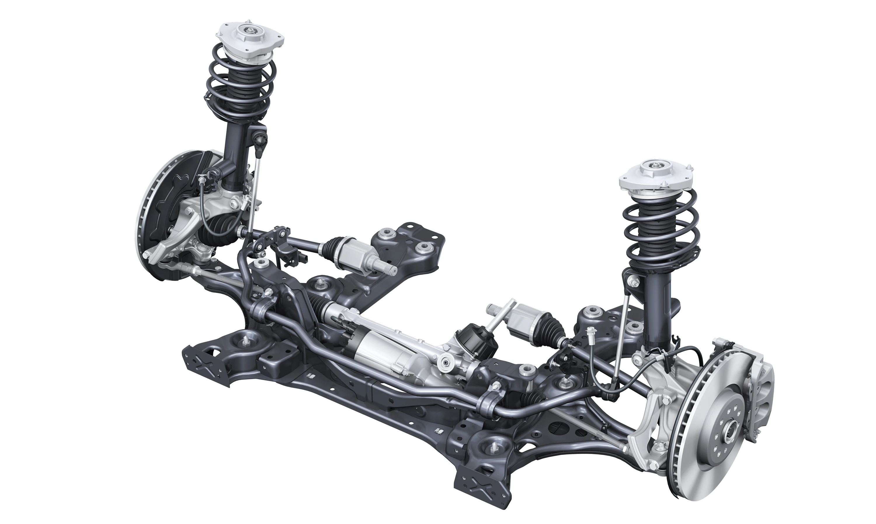
Its strengths are low part count, useful lateral packaging and space between the suspension towers for crash structure, drive components or a front cargo compartment. Its constraints include a high structural load through the strut and top mount, sensitivity to friction and mount stiffness, and less independent control of camber and steering-axis geometry than layouts with separate upper links.
“Double-joint,” “dual-axis” or “double-pivot” strut axles split the lower control function into two links and create a virtual lower steering point. They remain strut-family layouts, but the virtual pivot gives engineers more freedom over scrub radius, steering disturbance and force paths. BMW's own description of its double-joint spring-strut axle shows why it is misleading to reduce every strut layout to one lower wishbone. BMW: double-joint spring-strut and five-link axle construction
Double wishbone
A double-wishbone suspension locates the wheel with upper and lower arms. The arms do not have to be literal A-shapes; each may be split into separate links, and the spring and damper can act directly or through a rocker or pushrod.
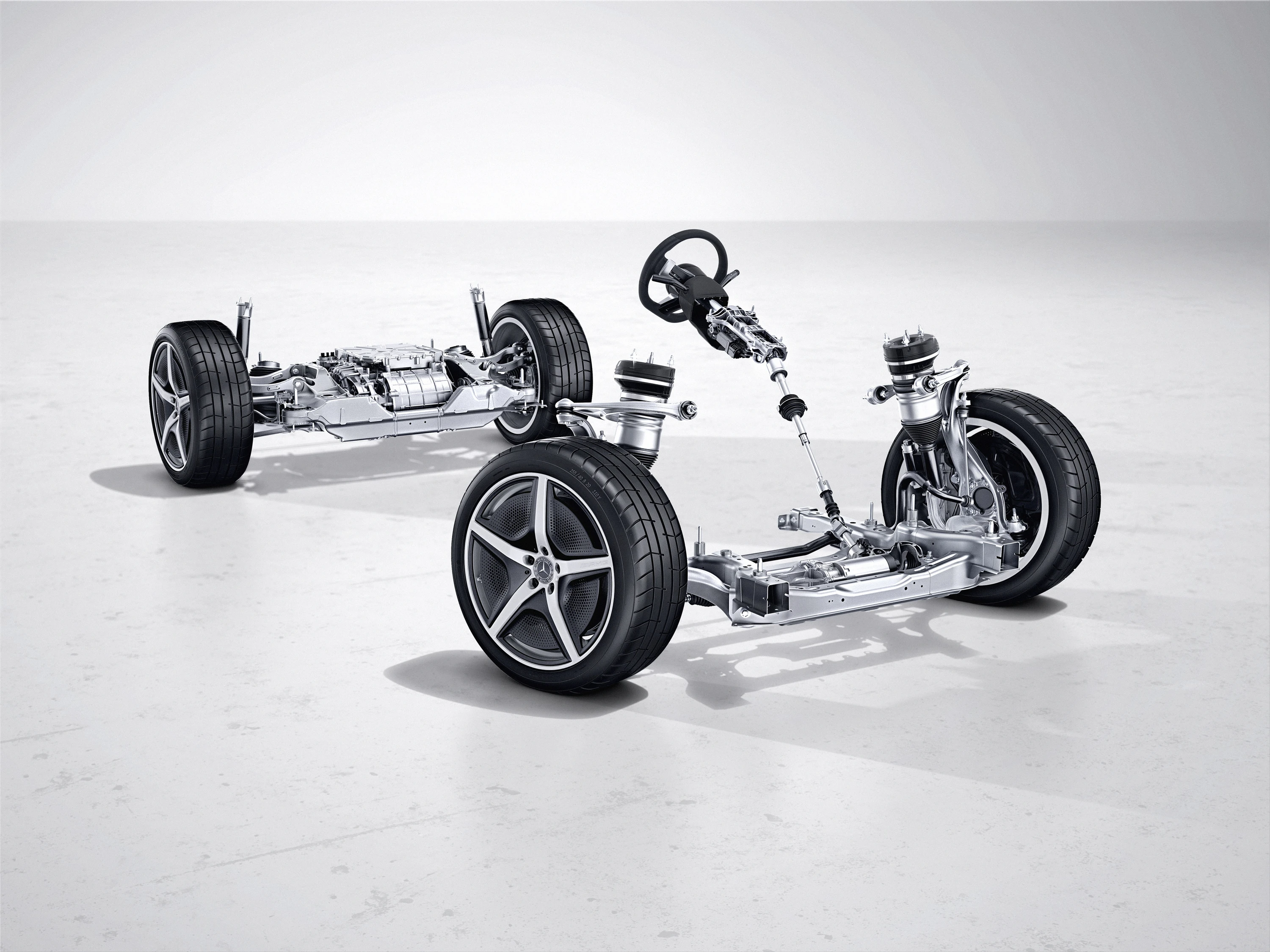
Separate upper and lower geometry gives engineers substantial freedom to shape camber gain, roll-centre movement, steering-axis position and anti-dive or anti-squat. It can also provide a stiff wheel-control structure with the damper separated from steering loads.
The cost is space and component count. An upper arm competes with the tyre envelope, body structure and front cargo space; short arms can create aggressive geometry change, while long arms need room. A badly chosen wishbone geometry is not rescued by the label.
Multi-link
“Multi-link” describes a family, not one standard mechanism. Separate links control different combinations of longitudinal, lateral and rotational motion. Their positions, joint types and stiffnesses determine the result.
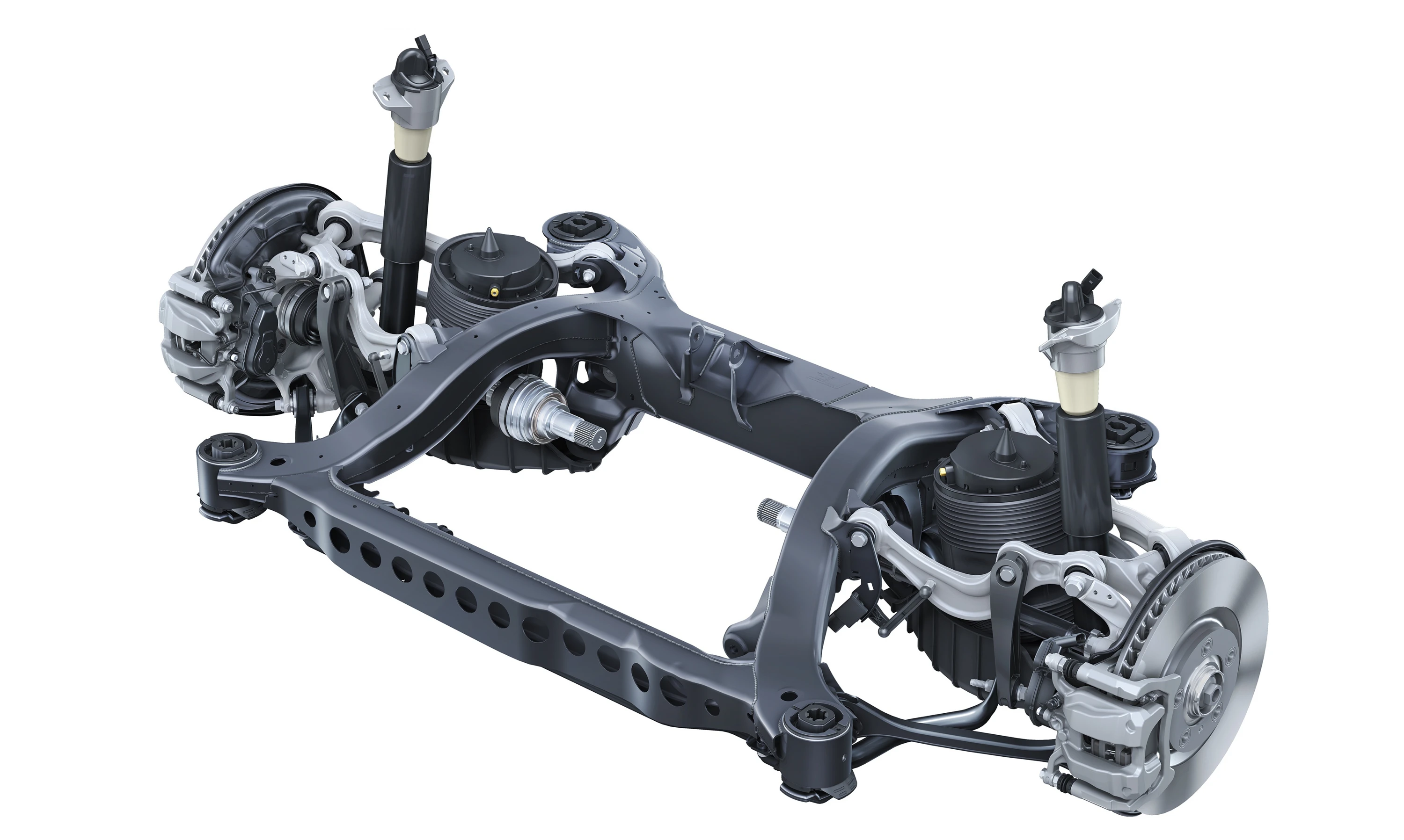
A five-link wheel-control system often uses five independent links to constrain five of the wheel carrier's six degrees of freedom, leaving the intended suspension motion. Real designs are less tidy than that textbook description: a wishbone may count as one arm or two links, a toe link may steer actively, and manufacturers use different naming conventions.
The value of a multi-link layout is tuning freedom. Engineers can separate toe control from camber control, direct braking and drive forces through different bushings, and place the spring and damper to suit cargo or motor packaging. The costs are more joints, tighter tolerance management, greater alignment complexity and more opportunities for compliance or wear to alter behavior.
The current Porsche Taycan demonstrates the distinction between a category and its execution: Porsche specifies double-wishbone front wheel control and a forged-aluminium multi-link rear, then combines those layouts with air springs and controlled dampers. The construction does not tell the reader which spring or damper technology is fitted. Porsche: Taycan front and rear suspension construction
Trailing arms and twist beams
A trailing arm pivots primarily around a transverse axis ahead of the wheel. It is compact and structurally direct for longitudinal loads, but a simple version offers limited independent control of camber and toe. Semi-trailing arms angle the pivot axis and deliberately couple wheel travel to camber and toe change.
A twist beam connects two trailing arms with a cross-member designed to twist. That member locates the wheels and supplies part of the axle's roll stiffness, which can eliminate a separate anti-roll bar.
The layout is compact, light in parts and cost-effective, and it can leave valuable underfloor and cargo space. Its wheel motions and compliance are more strongly coupled than those of a fully independent axle, and high rear axle load or demanding ride-and-handling targets can make the beam, bushes and body attachments difficult to optimize simultaneously. Engineering studies nevertheless show that cross-member geometry and bush orientation offer meaningful tuning scope; “torsion beam” is not a complete verdict on the chassis. SAE: rear twist-beam geometry and bush optimization
Solid axles and leaf-spring location
A solid axle keeps the two wheels' camber relationship fixed to the axle and provides strong, simple load paths. It remains relevant to vans, pickups and off-road vehicles where payload, towing, articulation and durability can outweigh unsprung-mass and isolation disadvantages.
Leaf springs can both support the body and locate an axle longitudinally, reducing the number of links. More sophisticated dependent axles use separate control arms, a Panhard rod or a Watt linkage to locate the axle while coil or air springs carry the load.
Because the differential and much of the driveline move with a live axle, unsprung mass can be high. A De Dion axle keeps the differential on the body side, reducing that penalty while retaining lateral coupling between the wheels.
Geometry is not calibration
Two EVs with the same advertised layout can behave differently because of:
- spring and damper motion ratios;
- static ride height and usable bump and rebound travel;
- bushing rate, directionality and friction;
- subframe and body-attachment stiffness;
- anti-roll-bar rate and mounting compliance;
- wheel offset, tyre construction, pressure and unsprung mass;
- alignment targets and tolerances;
- steering, braking and active-chassis software.
That is why suspension springs, suspension dampers and active suspension are separate parts of this series.
What buyers and owners should check
Treat a layout name as a starting point. Look for the exact front and rear construction, whether rear steering or active toe control changes it, and whether optional suspension packages replace springs, dampers or both.
Wheel alignment should be evaluated at the specified ride height and load. Lowering, raising or fitting a different wheel offset can change camber, toe, bump steer, roll-centre position, driveshaft angles and remaining travel. Rubber-bushed links may also need to be tightened at the prescribed design position; clamping them at full droop can preload the bushes at normal ride height.
On the road, judge the result: steering precision over bumps, stability under braking, head toss on alternating inputs, tyre noise, impact isolation and the way the car settles. Architecture creates possibilities. Geometry, compliance and calibration decide how much of that potential reaches the driver.