
Suspension dampers: force, velocity and adaptive control
A damper controls suspension motion by resisting the relative velocity between the wheel assembly and the body. It converts mechanical work into heat, allowing the tyre and body to settle after a disturbance instead of continuing to oscillate on the springs.
Force, velocity and energy
For an ideal linear viscous damper:
F_d = c × v
F_d is damper force in newtons, c is the damping coefficient in N·s/m, and v is the relative velocity across the damper in m/s. The instantaneous rate at which it dissipates energy is approximately:
P = F_d × v
Real automotive dampers are deliberately nonlinear. Their force depends on velocity, direction, stroke position, temperature, pressure, acceleration history, valve hysteresis, friction and aeration. The linear equation explains the principle, not a production damper's full behavior.
Damping must balance three competing outcomes: body acceleration, suspension travel and variation in tyre load. Increasing damping does not improve all three at every frequency. A setting that arrests slow body motion can transmit more of a sharp road input; a setting that isolates that impact can allow more pitch, roll or float. The quarter-car analysis introduced in EV suspension overview shows why a single passive curve is always a compromise. SAE: dynamic behavior of passive and active suspension systems
Compression and rebound
Compression, or bump, is the stroke direction in which the damper shortens. Rebound, or extension, is the opposite direction. The same road event normally uses both: the wheel moves into bump as it climbs an obstacle and the suspension extends as the road falls away or the body rises.
Compression force helps control how quickly the wheel and body use their bump travel. Rebound force controls the release of energy stored in the spring. Too little rebound can allow repeated body oscillation; too much can prevent the wheel from extending quickly enough over a series of depressions and can progressively pull the suspension down into its travel, a behavior called packing.
Force is not judged by rebound-to-compression ratio alone. Motion ratio, spring rate, tyre stiffness, axle load, available travel and the shape of both force curves determine what the vehicle feels.
“Low-speed” and “high-speed” damping
These terms refer to damper-shaft velocity, not vehicle speed.
- Low shaft velocities are commonly associated with body heave, pitch, roll and gradual steering inputs.
- Higher shaft velocities are commonly created by sharp edges, potholes, surface joints and rapid wheel movement.
There is no universal velocity that separates the two. A damper dynamometer plot must be read with its test stroke, frequency, temperature and sign convention. A car travelling slowly can generate high damper velocity at a sharp edge, while a car travelling quickly on a smooth road can have low damper velocity.
Valve design shapes the force–velocity curve:
- A linear region increases force roughly in proportion to velocity.
- A digressive curve builds force quickly at low velocity and then reduces its rate of increase after a valve opens. This can combine body control with impact relief.
- A progressive curve increases force more steeply as velocity rises.
- A blow-off or relief circuit limits a force rise above a designed threshold.
Those words describe curve shape, not inherent quality. The transition force, smoothness, hysteresis and repeatability are at least as important as the category.
Inside a hydraulic damper
A piston moves through oil and forces it through calibrated bleed passages, shim stacks, ports and valves. Restricting that flow creates a pressure difference across the piston and therefore a force on the rod. Gas pressure helps accommodate the entering piston-rod volume and suppress cavitation or foaming.
In a monotube damper, the working piston and oil share one cylinder with a separating piston between the oil and a pressurized gas chamber. The large working piston and direct heat path can provide useful force capacity and thermal control, but gas force, seal friction, stone protection and installation package still require careful design.
In a twin-tube damper, an inner working tube is surrounded by a reservoir tube. Oil displaced by the rod passes through a base valve into the reservoir. This can offer compact packaging, lower gas pressure and useful ride characteristics. Orientation, aeration, piston area and heat rejection differ from a monotube design. Neither construction is automatically comfortable or sporting; Bilstein produces both and documents the distinct oil and gas paths. Bilstein: monotube and twin-tube damper construction
Remote reservoirs add fluid and gas volume and can improve heat capacity or packaging. Position-sensitive and bypass dampers use additional flow paths that open or close through the stroke, allowing different force near the centre and ends of travel.
Passive does not mean simple
A passive damper has no commanded external control input, but it can still change behavior mechanically.
Frequency-selective systems add an internal hydraulic path that responds differently to sustained low-frequency motion and shorter high-frequency inputs. KONI's Frequency Selective Damping is one documented example: it uses passive hydraulic control to provide a different response for body motion and road disturbance without sensors or an electronic valve. KONI: passive Frequency Selective Damping
Öhlins Dual Flow Valve dampers use additional compression and rebound flow paths to tune the intermediate shaft-speed range. The valve architecture remains passive while the mechanical setting may be adjustable. Öhlins: Dual Flow Valve damper technology
The Polestar 2 Performance Pack illustrates the distinction between adjustable and adaptive. Its Öhlins dampers have manual click settings at each corner. Once set, they do not change themselves in real time. Polestar specifies matched front and rear settings for track, nominal and comfort use, and its access procedure shows that adjustment is an ownership task rather than a dashboard mode. Polestar 2 manual: adjustable Öhlins damper settings
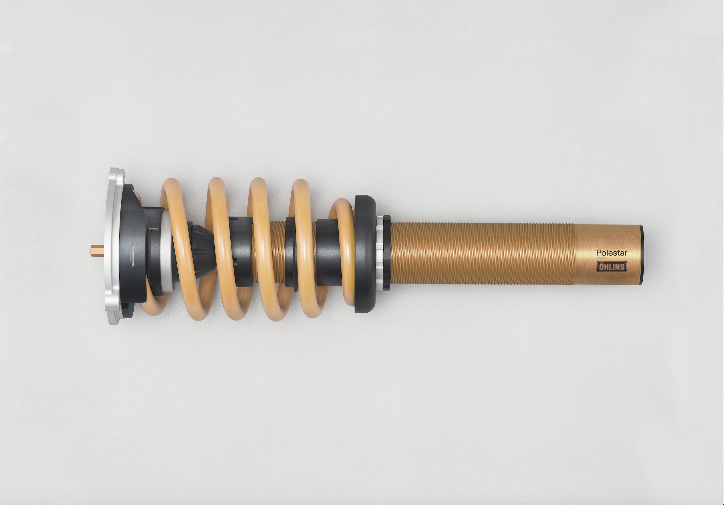
Manual adjustment should follow the vehicle maker's procedure. Unequal left-right settings, forcing an adjuster past its stop or changing damping without considering tyres and springs can create inconsistent behavior.
Electronically controlled damping
A semi-active damper changes its force characteristic in response to a controller but, in the usual definition, does not command an arbitrary force independent of suspension motion. It can resist relative motion more or less strongly; it cannot behave like a powered jack whenever the controller wishes.
Hydraulic systems such as ZF Continuous Damping Control use proportional valves to vary flow at each wheel from sensor and vehicle-state data. Two-valve designs can control compression and rebound through separate external valves, increasing the available tuning freedom. ZF: Continuous Damping Control Porsche: Taycan two-valve adaptive dampers
Magnetorheological dampers use fluid containing magnetically responsive particles. A controlled magnetic field changes resistance to flow through the valve, varying damper force without a conventional moving proportional valve. The device is still semi-active: stroke velocity and the achievable force envelope constrain what it can produce. BWI Group: magnetorheological semi-active damping
Sensor rate or valve response time alone does not establish ride quality. The controller must estimate body and wheel motion, choose a realizable force, command the damper, and remain stable through delays, noise, temperature and rapidly changing grip. active suspension covers that control hierarchy and systems that can add mechanical energy.
Friction, temperature and fade
The ideal damper force is hydraulic, but seals, bearings and side loads add friction. High breakaway force can make the suspension reluctant to move over small inputs even if the dyno curve looks suitable after the shaft is moving. Strut bending loads, top mounts and bushings can increase this effect.
Every dissipated joule becomes heat. Rising oil temperature changes viscosity, gas pressure, seal behavior and valve response. Aeration or cavitation can reduce force and consistency. Monotube layout, fluid volume, reservoirs, cooling airflow and temperature-compensating valves are tools for controlling those changes, not guarantees against them.
A road-car damper therefore needs repeatable behavior from a cold start through prolonged rough-road or high-speed use. Peak force at one dyno point says little about thermal stability.
EV-specific calibration
An EV can ask more of its dampers without requiring a fundamentally different damper:
- Changes in mass and mass distribution alter the force and energy involved in heave, pitch and roll.
- Strong regeneration can create frequent, repeatable pitch inputs.
- Large wheel-and-tyre packages can demand more control of unsprung motion.
- A quiet powertrain makes seal noise, valve hiss, top-out knocks and impact noise easier to perceive.
- Battery protection and aerodynamic targets can restrict ride height or usable travel.
Adding damping is not a complete response to mass. If the spring, bump stop, tyre and travel are wrong, a stiffer curve may only convert uncontrolled motion into harshness.
What buyers and owners should check
When a specification says “adaptive suspension,” establish exactly what changes:
- Are the dampers continuously variable or switched between a few states?
- Are compression and rebound controlled separately?
- Does the option also replace the springs with air springs?
- Is adjustment automatic, tied to drive mode, manual at the damper, or some combination?
- Does a comfort mode isolate sharp inputs without allowing repeated body motion?
- Does a sport mode add useful control or merely transmit more road texture?
- Does the vehicle remain composed with its largest wheel option and normal passenger load?
Ageing dampers can leak, lose gas pressure, aerate, seize at mounts or wear internally. Symptoms can include repeated bouncing, wheel hop, uneven tyre wear, knocks, unstable response to crosswinds or braking, and oil contamination on the damper body. These symptoms are not unique to dampers, so springs, tyres, joints, bushings and alignment should be inspected as a system.
Sources
- SAE: dynamic behavior of passive and active suspension systems
- Bilstein: monotube and twin-tube damper construction
- KONI: passive Frequency Selective Damping
- Öhlins: Dual Flow Valve damper technology
- Polestar 2 manual: adjustable Öhlins damper settings
- ZF: Continuous Damping Control
- BWI Group: magnetorheological semi-active damping
- Porsche: Taycan two-valve adaptive dampers